Indiquez-nous le code erreur ou le problème rencontré
pour obtenir un diagnostic ou un devis de réparation.
Codes erreur les plus fréquents
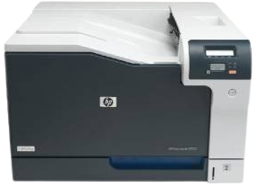
Imprimante HP Color LaserJet Professional CP5225, CP5225N, CP5225DN
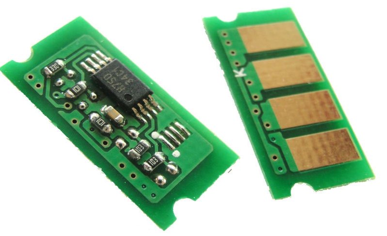
Code Erreur 10 ou Erreur mémoire consommable 
Code Erreur 13.xx ou Bourrage papier 
Code Erreur 49 
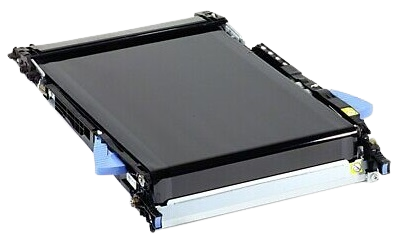
Code Erreur 50 ou Erreur Station fusion ou Remplacer kit de maintenance 
Message Bac récup toner plein 
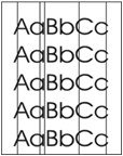
Message Traces grisâtres à l'impression 
Problèmes les plus fréquemment rencontrés
Imprimante HP Color LaserJet Professional CP5225, CP5225N, CP5225DN
Tableau de tous les codes erreurs
Imprimante HP Color LaserJet Professional CP5225, CP5225N, CP5225DN
- code :
-
- affichage :
Unexpected size in tray # Load <size> press [OK]
- description :
SIZE MISMATCH message appears although the media is loaded on the configured pickup source with correct size
- remede :
1. Run the switch test in the sensor monitor mode to verify that the corresponding media width switch and media end width switch are functioning correctly. 2. Reconnect the corresponding connector of the switch: • Printer cassette: Intermediate connector (J742) and the connector (J151) on the DC controller PCA. • PF cassette: Connector (J2007) on the PF controller PCA.
- code :
10.10.XX
- affichage :
10.10.XX Supply error
- description :
• 10.1000 = black supply memory is missing • 10.1001 = cyan supply memory is missing • 10.1002 = magenta supply memory is missing • 10.1003 = yellow supply memory is missing
- remede :
Check the e-label. If it is broken or damaged, replace the cartridge. Verify that the cartridge is installed in the correct location. Remove and reinstall the cartridge and then power-cycle the product. If the error is with a color cartridge, try swapping it with a different color cartridge in the tray. If the same message appears, then there is an engine problem. If a different 10.10.XX message appears, replace the cartridge.
- code :
10.9531
- affichage :
10.9531 Error
- description :
The toner collection unit is full or missing.
- remede :
Replace the toner collection unit.
- code :
10.XXXX
- affichage :
10.XXXX Supply error
- description :
The supply memory for one of the print cartridges cannot be read or is missing. • 10.0000 = black supply memory error • 10.0001 = cyan supply memory error • 10.0002 = magenta supply memory error • 10.0003 = yellow supply memory error
- remede :
Reinstall the print cartridge. Turn the product off and then on. If the problem is not solved, replace the cartridge.
- code :
50.1
- affichage :
50.1 Fuser Error
- description :
Abnormally low fuser temperature.
- remede :
1. Remove the fuser and check for any residual media in the fuser. Remove any residual media. 2. Reinstall the fuser. Check the connector (J704) between the fuser and the product. If it is damaged, replace the fuser drive unit or fuser. 3. Reconnect the connector (J131A) on the DC controller PCA and the connectors (J109, J110) on the power line between the low-voltage power supply unit and fuser. 4. Replace the fuser.
- code :
50.2
- affichage :
50.2 Fuser Error
- description :
Fuser warm-up failure.
- remede :
1. Reinstall the fuser. Check the connector (J704) between the fuser and the product. If it is damaged, replace the fuser drive unit or the fuser. 2. Reconnect the connector (J131A) on the DC controller PCA and the connectors (J109, J110) on the power line between the low-voltage power supply unit and fuser. 3. Replace the fuser.
- code :
50.3
- affichage :
50.3 Fuser Error
- description :
Abnormally high fuser temperature.
- remede :
1. Reinstall the fuser. Check the connector (J704) between the fuser and the product. If it is damaged, replace the fuser drive unit or fuser. 2. Reconnect the connector (J131A) on the DC controller PCA. 3. Replace the fuser.
- code :
50.4
- affichage :
50.4 Fuser Error
- description :
Fuser drive circuit is defective.
- remede :
1. Check the power source at the product location. NOTE: If the product does not meet the power requirement of 43 to 57Hz frequency, the fuser temperature control does not work correctly and this causes malfunction. 2. Reconnect the connector (J21) on the DC controller PCA. 3. Replace the low-voltage power supply unit.
- code :
50.7
- affichage :
50.7 Fuser Error
- description :
The fuser is defective (pressure release mechanism abnormality).
- remede :
1. Reconnect the connector (J181) on the DC controller PCA. 2. Run the sensor test in the sensor monitor mode to verify that the fuser pressure release sensor is functioning correctly. If it is not, replace the fuser pressure release sensor unit. 3. Check the fuser pressure release sensor flag. If it is damaged, replace the fuser. 4. Run the fuser pressure release drive test in the actuator drive mode to verify that the fuser motor is functioning correctly. If it is not, replace the fuser mot
- code :
50.8
- affichage :
50.8 Fuser Error
- description :
Abnormally low subthermistor fuser temperature error.
- remede :
1. Remove the fuser and remove any residual media in the fuser. 2. Reinstall the fuser. Check the connector (J704) between the fuser and the product. If it is damaged, replace the fuser drive unit or fuser. 3. Reconnect the connector (J131A) on the DC controller PCA and the connectors (J109, J110) on the power line between the low-voltage power supply unit and fuser. 4. Replace the fuser.
- code :
50.9
- affichage :
50.9 Fuser Error
- description :
Abnormally high subthermistor fuser temperature error.
- remede :
1. Reinstall the fuser. Check the connector (J704) between the fuser and the product. If it is damaged, replace the fuser drive unit or fuser. 2. Reconnect the connector (J131A) on the DC controller PCA. 3. Replace the fuser.
- code :
51.20
- affichage :
51.XX Error
- description :
The product has experienced an internal error with a laser scanner. black
- remede :
1. Turn the product off and then on. 2. Verify that the connectors J61 and J62 on the DC controller PCA are correctly seated. Also verify that the connectors on the laser scanner are correctly seated. 3. If the problem remains, replace the laser scanner.
- code :
51.21
- affichage :
51.XX Error
- description :
The product has experienced an internal error with a laser scanner. cyan
- remede :
1. Turn the product off and then on. 2. Verify that the connectors J61 and J62 on the DC controller PCA are correctly seated. Also verify that the connectors on the laser scanner are correctly seated. 3. If the problem remains, replace the laser scanner.
- code :
51.22
- affichage :
51.XX Error
- description :
The product has experienced an internal error with a laser scanner. magenta
- remede :
1. Turn the product off and then on. 2. Verify that the connectors J61 and J62 on the DC controller PCA are correctly seated. Also verify that the connectors on the laser scanner are correctly seated. 3. If the problem remains, replace the laser scanner.
- code :
51.23
- affichage :
51.XX Error
- description :
The product has experienced an internal error with a laser scanner. yellow
- remede :
1. Turn the product off and then on. 2. Verify that the connectors J61 and J62 on the DC controller PCA are correctly seated. Also verify that the connectors on the laser scanner are correctly seated. 3. If the problem remains, replace the laser scanner.
- code :
54.15
- affichage :
54.XX Error
- description :
The product has experienced an error with one of the print cartridge sensors. yellow
- remede :
1. Open the door to the cartridge tray and slide out the cartridge tray. 2. Inspect the white mechanism on the relevant cartridge. It is located on the right side of the cartridge. 3. Push the mechanism in and out slowly. A black flag will raise up as you push it. If it does not move smoothly, push repeatedly to try to clear any potential obstruction. 4. Push in the cartridge tray and close the door.
- code :
54.16
- affichage :
54.XX Error
- description :
The product has experienced an error with one of the print cartridge sensors. magenta
- remede :
1. Open the door to the cartridge tray and slide out the cartridge tray. 2. Inspect the white mechanism on the relevant cartridge. It is located on the right side of the cartridge. 3. Push the mechanism in and out slowly. A black flag will raise up as you push it. If it does not move smoothly, push repeatedly to try to clear any potential obstruction. 4. Push in the cartridge tray and close the door.
- code :
54.17
- affichage :
54.XX Error
- description :
The product has experienced an error with one of the print cartridge sensors. cyan
- remede :
1. Open the door to the cartridge tray and slide out the cartridge tray. 2. Inspect the white mechanism on the relevant cartridge. It is located on the right side of the cartridge. 3. Push the mechanism in and out slowly. A black flag will raise up as you push it. If it does not move smoothly, push repeatedly to try to clear any potential obstruction. 4. Push in the cartridge tray and close the door.
- code :
54.18
- affichage :
54.XX Error
- description :
The product has experienced an error with one of the print cartridge sensors. black
- remede :
1. Open the door to the cartridge tray and slide out the cartridge tray. 2. Inspect the white mechanism on the relevant cartridge. It is located on the right side of the cartridge. 3. Push the mechanism in and out slowly. A black flag will raise up as you push it. If it does not move smoothly, push repeatedly to try to clear any potential obstruction. 4. Push in the cartridge tray and close the door.
- code :
55.0601
- affichage :
55.X Error
- description :
DC controller NVRAM data error
- remede :
1. Turn the product off and on. If the problem remains, replace the DC controller PCA.
- code :
55.0602
- affichage :
55.X Error
- description :
DC controller NVRAM access error
- remede :
1. Turn the product off and on. If the problem remains, replace the DC controller PCA.
- code :
55.1
- affichage :
55.X Error
- description :
DC controller memory error
- remede :
1. Turn the product off and on. If the problem remains, replace the DC controller PCA.
- code :
55.3
- affichage :
55.X Error
- description :
Engine communication error
- remede :
1. Turn the product off and on. If the problem remains, replace the DC controller PCA.
- code :
55.4
- affichage :
55.X Error
- description :
Engine timeout error
- remede :
1. Turn the product off and on. If the problem remains, replace the DC controller PCA.
- code :
56.X
- affichage :
56.X Error
- description :
Tray <X> not correctly installed.
- remede :
Reinstall the tray.
- code :
57.01
- affichage :
57.01 Error
- description :
Power supply fan (FM1) is defective.
- remede :
1. Reconnect the connector (J21) on the DC controller PCA and the connector (J106) on the low-voltage power supply unit. 2. Measure the voltage between the connector J21-2 and J25-2 on the DC controller PCA right after the product is turned on. If the voltage changes from 0 V to approximately 24 V, replace the power supply fan.
- code :
57.02
- affichage :
57.02 Error
- description :
The fuser fan (FM2) is defective
- remede :
1. Reconnect the connector (J121X) on the DC controller PCA and the intermediate connector (J524). 2. Measure the voltage between the connector J121X-6 and J121X-4 on the DC controller PCA right after the product is turned on. If the voltage changes from 0 V to approximately 24 V, replace the fixing fan.
- code :
58.04
- affichage :
58.04 Error
- description :
Low-voltage power supply malfunction.
- remede :
1. Turn the product off and then on. 2. Verify that connectors J21 and J25 on the DC controller PCA are correctly seated. Also verify that all connectors on the lowvoltage power supply are correctly seated. 3. If the problem remains, replace the low-voltage power supply.
- code :
59.3
- affichage :
59.X Error
- description :
The product has experienced a problem with one of the motors. - Fuser motor startup error
- remede :
1. Reconnect the connector (J516) on the fuser motor and the connector (J81) on the DC controller PCA. 2. Run the fuser motor drive test in the actuator drive mode to verify that the fuser motor is functioning correctly. If it is not, replace the fuser motor unit.
- code :
59.4
- affichage :
59.X Error
- description :
The product has experienced a problem with one of the motors. - Fuser motor rotation error.
- remede :
1. Reconnect the connector (J516) on the fuser motor and the connector (J81) on the DC controller PCA. 2. Run the fuser motor drive test in the actuator drive mode to verify that the fuser motor is functioning correctly. If it is not, replace the fuser motor unit.
- code :
59.50
- affichage :
59.X Error
- description :
Image drum motor startup or rotation error-black. - Image drum motor startup error-black
- remede :
1. Reconnect the connector (J517) on the ITB motor and the connector (J81) on the DC controller PCA. 2. Run the drum motor drive test in the actuator drive mode to verify that the ITB motor is functioning correctly. If it is not, replace the ITB motor unit.
- code :
59.51
- affichage :
59.X Error
- description :
Image drum motor startup or rotation error-cyan, magenta, or yellow. - Image drum motor startup error-cyan
- remede :
1. Reconnect the connector (J515) on the drum motor and the connector (J81) on the DC controller PCA. 2. Run the drum motor drive test in the actuator drive mode to verify that the drum motor is functioning correctly. If it is not, replace the drum motor unit.
- code :
59.52
- affichage :
59.X Error
- description :
Image drum motor startup or rotation error-cyan, magenta, or yellow. - Image drum motor startup error-magenta
- remede :
1. Reconnect the connector (J515) on the drum motor and the connector (J81) on the DC controller PCA. 2. Run the drum motor drive test in the actuator drive mode to verify that the drum motor is functioning correctly. If it is not, replace the drum motor unit.
- code :
59.53
- affichage :
59.X Error
- description :
Image drum motor startup or rotation error-cyan, magenta, or yellow. - Image drum motor startup error-yellow
- remede :
1. Reconnect the connector (J515) on the drum motor and the connector (J81) on the DC controller PCA. 2. Run the drum motor drive test in the actuator drive mode to verify that the drum motor is functioning correctly. If it is not, replace the drum motor unit.
- code :
59.60
- affichage :
59.X Error
- description :
Image drum motor startup or rotation error-black. - Image drum motor rotation error-black
- remede :
1. Reconnect the connector (J517) on the ITB motor and the connector (J81) on the DC controller PCA. 2. Run the drum motor drive test in the actuator drive mode to verify that the ITB motor is functioning correctly. If it is not, replace the ITB motor unit.
- code :
59.61
- affichage :
59.X Error
- description :
Image drum motor startup or rotation error-cyan, magenta, or yellow. - Image drum motor rotation error-cyan
- remede :
1. Reconnect the connector (J515) on the drum motor and the connector (J81) on the DC controller PCA. 2. Run the drum motor drive test in the actuator drive mode to verify that the drum motor is functioning correctly. If it is not, replace the drum motor unit.
- code :
59.62
- affichage :
59.X Error
- description :
Image drum motor startup or rotation error-cyan, magenta, or yellow. - Image drum motor rotation error-magenta
- remede :
1. Reconnect the connector (J515) on the drum motor and the connector (J81) on the DC controller PCA. 2. Run the drum motor drive test in the actuator drive mode to verify that the drum motor is functioning correctly. If it is not, replace the drum motor unit.
- code :
59.63
- affichage :
59.X Error
- description :
Image drum motor startup or rotation error-cyan, magenta, or yellow. - Image drum motor rotation error-yellow
- remede :
1. Reconnect the connector (J515) on the drum motor and the connector (J81) on the DC controller PCA. 2. Run the drum motor drive test in the actuator drive mode to verify that the drum motor is functioning correctly. If it is not, replace the drum motor unit.
- code :
59.70
- affichage :
59.X Error
- description :
Developing motor abnormal rotation or start-up. - Black developer motor startup error
- remede :
1. Reconnect the connector (J514) on the developing motor and the connector (J81) on the DC controller PCA. 2. Run the developing motor drive test in the actuator drive mode to verify that the developing motor is functioning correctly. If it is not functioning correctly, replace the developing motor unit.
- code :
59.71
- affichage :
59.X Error
- description :
Developing motor abnormal rotation or start-up. - Cyan developer motor startup error
- remede :
1. Reconnect the connector (J514) on the developing motor and the connector (J81) on the DC controller PCA. 2. Run the developing motor drive test in the actuator drive mode to verify that the developing motor is functioning correctly. If it is not functioning correctly, replace the developing motor unit.
- code :
59.72
- affichage :
59.X Error
- description :
Developing motor abnormal rotation or start-up. - Magenta developer motor startup error
- remede :
1. Reconnect the connector (J514) on the developing motor and the connector (J81) on the DC controller PCA. 2. Run the developing motor drive test in the actuator drive mode to verify that the developing motor is functioning correctly. If it is not functioning correctly, replace the developing motor unit.
- code :
59.73
- affichage :
59.X Error
- description :
Developing motor abnormal rotation or start-up. - Yellow developer motor startup error
- remede :
1. Reconnect the connector (J514) on the developing motor and the connector (J81) on the DC controller PCA. 2. Run the developing motor drive test in the actuator drive mode to verify that the developing motor is functioning correctly. If it is not functioning correctly, replace the developing motor unit.
- code :
59.80
- affichage :
59.X Error
- description :
Developing motor abnormal rotation or start-up. - Black developer motor rotation error
- remede :
1. Reconnect the connector (J514) on the developing motor and the connector (J81) on the DC controller PCA. 2. Run the developing motor drive test in the actuator drive mode to verify that the developing motor is functioning correctly. If it is not functioning correctly, replace the developing motor unit.
- code :
59.81
- affichage :
59.X Error
- description :
Developing motor abnormal rotation or start-up. - Cyan developer motor rotation error
- remede :
1. Reconnect the connector (J514) on the developing motor and the connector (J81) on the DC controller PCA. 2. Run the developing motor drive test in the actuator drive mode to verify that the developing motor is functioning correctly. If it is not functioning correctly, replace the developing motor unit.
- code :
59.82
- affichage :
59.X Error
- description :
Developing motor abnormal rotation or start-up. - Magenta developer motor rotation error
- remede :
1. Reconnect the connector (J514) on the developing motor and the connector (J81) on the DC controller PCA. 2. Run the developing motor drive test in the actuator drive mode to verify that the developing motor is functioning correctly. If it is not functioning correctly, replace the developing motor unit.
- code :
59.83
- affichage :
59.X Error
- description :
Developing motor abnormal rotation or start-up. - Yellow developer motor rotation error
- remede :
1. Reconnect the connector (J514) on the developing motor and the connector (J81) on the DC controller PCA. 2. Run the developing motor drive test in the actuator drive mode to verify that the developing motor is functioning correctly. If it is not functioning correctly, replace the developing motor unit.
- code :
59.9
- affichage :
59.X Error
- description :
ITB motor start error or rotation error. - ITB motor start error
- remede :
1. Reconnect the connector (J517) on the ITB motor and the connector (J81) on the DC controller PCA. 2. Run the ITB motor drive test in the actuator drive mode to verify that the ITB motor is functioning correctly. If it is not functioning correctly, replace the ITB motor unit.
- code :
59.A0
- affichage :
59.X Error
- description :
ITB motor start error or rotation error. - ITB motor rotation error
- remede :
1. Reconnect the connector (J517) on the ITB motor and the connector (J81) on the DC controller PCA. 2. Run the ITB motor drive test in the actuator drive mode to verify that the ITB motor is functioning correctly. If it is not functioning correctly, replace the ITB motor unit.
- code :
59.C0
- affichage :
59.C0 Error
- description :
Developer motor rotation error.
- remede :
1. Reconnect the connector (J518) on the developing disengagement motor, the connector (J1005) on the driver PCA and the connector (J91) on the DC controller PCA. 2. Run the sensor test in the sensor monitor mode to verify that the developing disengagement sensor is functioning correctly. If it is not, replace the developing disengagement sensor unit. 3. Run the developing unit engagement and disengagement drive test in the actuator drive mode to verify that the disengagement mechanism is fun
- code :
59.F0
- affichage :
59.F0 Error
- description :
Transfer alienation failure.
- remede :
1. Check if the ITB unit is installed. 2. Reconnect the connector (J181) on the DC controller PCA. 3. Run the switch test in the sensor monitor mode to verify that the primary transfer roller disengagement switch is functioning correctly. If it is not functioning correctly, replace the primary transfer roller disengagement switch unit. 4. Run the primary transfer roller engagement and disengagement drive test in the actuator drive mode to verify that the primary transfer roller disengagement


