Indiquez-nous le code erreur ou le problème rencontré
pour obtenir un diagnostic ou un devis de réparation.
Codes erreur les plus fréquents
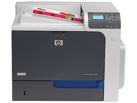
Imprimante HP Color LaserJet Enterprise CP4025, CP4025N, CP4025DN
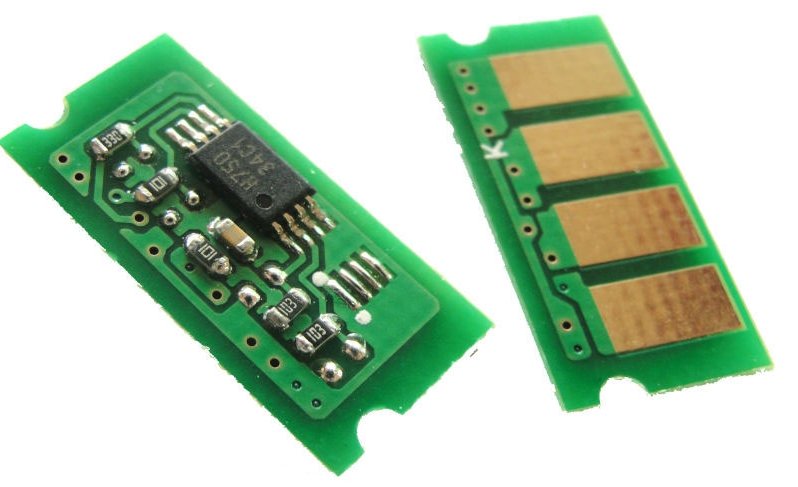
Code Erreur 10 ou Erreur mémoire consommable 
Code Erreur 13.xx ou Bourrage papier 
Code Erreur 49 
Code Erreur 50 ou Erreur Station fusion ou Remplacer kit de maintenance 
Code Erreur 59.F0 
Message Bac récup toner plein 
Problèmes les plus fréquemment rencontrés
Imprimante HP Color LaserJet Enterprise CP4025, CP4025N, CP4025DN
Tableau de tous les codes erreurs
Imprimante HP Color LaserJet Enterprise CP4025, CP4025N, CP4025DN
- code :
-
- affichage :
CLOSE RIGHT DOOR
- description :
A door on the right side of the product is open.
- remede :
1. Close the door. 2. Run the switch test in the sensor monitor mode to verify that the right-door switch is functioning properly. 3. Reconnect connectors J43 of the rightdoor switch and connector J147 on the DC controller PCA. 4. If the message persists, check the right door sensor flag. If it is damaged, replace the right door.
- code :
10.XX.YY
- affichage :
10.XX.YY SUPPLY MEMORY ERROR
- description :
The product cannot read or write to at least one print cartridge memory tag or a memory tag is missing from a print cartridge. XX values • 00 = Memory tag memory error • 10 = Memory tag missing YY values • 00 = Black • 01 = Cyan • 02 = Magenta • 03 = Yellow
- remede :
Reinstall the print cartridge, or install a new print cartridge.
- code :
11.01
- affichage :
11.XX Internal clock error
- description :
The product real-time clock has experienced an error. clock battery failed
- remede :
Whenever the product is turned off and then turned on again, set the time and date at the control panel.
- code :
11.02
- affichage :
11.XX Internal clock error
- description :
The product real-time clock has experienced an error. real time clock failed
- remede :
Whenever the product is turned off and then turned on again, set the time and date at the control panel.
- code :
13.XX.YY
- affichage :
13.XX.YY JAMS IN RIGHT DOOR
- description :
A jam has occurred in the fuser area.
- remede :
CAUTION: The fuser can be hot while the product is in use. Wait for the fuser to cool before handling it.
- code :
20
- affichage :
20 INSUFFICIENT MEMORY
- description :
The product received more data than can fit in the available memory. You might have tried to transfer too many macros, soft fonts, or complex graphics.
- remede :
Press the OK button to print the transferred data (some data might be lost), and then simplify the print job or install additional memory.
- code :
21.X
- affichage :
21.X INSUFFICIENT MEMORY TO LOAD FONTS/DATA
- description :
Insufficient memory to process the print job.
- remede :
Install additional memory in the product.job.
- code :
22
- affichage :
22 USB I/O BUFFER OVERFLOW
- description :
The product's USB buffer has overflowed.
- remede :
Press the OK button to print the transferred data. (Some data might be lost.) Check the host configuration.
- code :
40
- affichage :
40 EMBEDDED I/O BAD TRANSMISSION
- description :
A temporary printing error has occurred.
- remede :
Press the OK button to clear the error message. (Data will be lost.)
- code :
41.3
- affichage :
41.3 UNEXPECTED SIZE IN TRAY <X> LOAD TRAY <X> [TYPE] [SIZE]
- description :
This message appears even though the tray is loaded with the correct paper size.
- remede :
1. Run the sensor test in the sensor monitor mode to verify that the cassette media size switch is functioning properly. 2. Reconnect the cassette media size switch intermediate connector J57, and connector J107 on the DC controller PCA. 3. Replace the lifter assembly.
- code :
41.5
- affichage :
41.5 UNEXPECTED TYPE IN TRAY <X> LOAD TRAY <X> [TYPE] [SIZE]
- description :
This message appears even though the tray is loaded with the correct paper size.
- remede :
1. Reconnect the media sensor intermediate connector J77, and connector J131 on the DC controller PCA. 2. Replace the registration assembly.
- code :
41.7
- affichage :
41.7 ERROR
- description :
Printer error • X = 2; beam detected misprint • X = 7; media transport error
- remede :
Turn the product off, and then on.
- code :
48.0
- affichage :
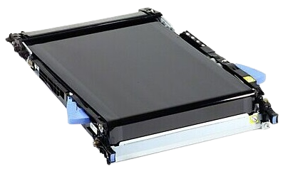
48.01 TRANSFER UNIT ERROR
- description :
The transfer belt has dislocated during printing.
- remede :
Turn product off then on. If the message persists, remove and reinstall the transfer unit.
- code :
49.XXXX
- affichage :
49.XXXX ERROR
- description :
A firmware error has occurred.
- remede :
jobs, software applications issues, nonproduct specific printer drivers, poor-quality USB or network cables, bad network connections or incorrect configurations, invalid firmware operations, or unsupported accessories. 1. Turn the product off and then on. 2. If the error returns, check the following items: • The error might be caused by a network connectivity problem, such as a bad interface cable, a bad USB port, or an invalid network configuration setting. • The error might be cau
- code :
50.1
- affichage :
50.1 FUSER ERROR
- description :
Low fuser temperature
- remede :
Remove the fuser and any residual paper. Check connector J50 between the fuser and the product. If either is damaged, replace the connector or fuser.
- code :
50.2
- affichage :
50.2 FUSER ERROR
- description :
Fuser warm-up failure
- remede :
1. Reinstall the fuser. 2. Check the connector J50 between the fuser and the product. If either is damaged, replace the connector or fuser. 3. Reconnect the connectors J160 and J162 on the DC controller PCA and connector J25 on the power line between the low voltage power supply and fuser. 4. Replace the wire harness that connects the fuser. 5. Replace the fuser. 6. If the error persists, replace the lowvoltage power supply.
- code :
50.3
- affichage :
50.3 FUSER ERROR
- description :
High fuser temperature
- remede :
Reinstall the fuser. Check connector J50 between the fuser and the product. If either is damaged, replace the connector or fuser. If the error persists, replace the low-voltage power supply.
- code :
50.4
- affichage :
50.4 FUSER ERROR
- description :
Drive circuit fault
- remede :
1. Check the power source. Make sure the power source meets product requirements. 2. Reconnect the connector J150 on the DC controller PCA. 3. If the message persists, replace the lowvoltage power supply.
- code :
50.5
- affichage :
50.5 FUSER ERROR
- description :
The incorrect fuser was installed.
- remede :
CAUTION: The fuser can be hot while the product is in use. Wait for the fuser to cool before handling it. 1. Open the right door. 2. Remove the incompatible fuser. 3. Install the correct fuser. 4. Close the right door.
- code :
50.7
- affichage :
50.7 FUSER ERROR
- description :
Fuser pressure-release mechanism failure
- remede :
1. Reconnect the fuser-pressure release sensor intermediate connector J60, and connector J128 on the DC controller PCA. 2. Run the sensor test in the sensor monitor mode to verify that the fuser pressure-release sensor is functioning properly. If it is not, replace the fuser pressure-release sensor. 3. Check the fuser pressure-release sensor flag. If it is damaged, replace the fuser. 4. Run the fuser pressure-release drive test in actuator drive mode to verify that the fuser motor is function
- code :
50.8
- affichage :
50.8 FUSER ERROR
- description :
Low fuser temperature.
- remede :
Remove the fuser and any residual paper. Check connector J50 between the fuser and the product. If either is damaged, replace the connector or fuser.
- code :
50.9
- affichage :
50.9 FUSER ERROR
- description :
High fuser temperature.
- remede :
Reinstall the fuser. Check the connector J50 between the fuser and the product. If either is damaged, replace the connector or fuser. If the error persists, replace the low-voltage power supply.
- code :
50.X
- affichage :
50.X FUSER ERROR
- description :
A fuser error has occurred.
- remede :
Make sure you have the correct fuser. Reseat the fuser. Turn the product off, and then turn the product on.
- code :
51.20
- affichage :
51.XY ERROR
- description :
black laser error
- remede :
Turn the product off, and then turn the product on.
- code :
51.21
- affichage :
51.XY ERROR
- description :
cyan laser error
- remede :
Turn the product off, and then turn the product on.
- code :
51.22
- affichage :
51.XY ERROR
- description :
magenta laser error
- remede :
Turn the product off, and then turn the product on.
- code :
51.23
- affichage :
51.XY ERROR
- description :
yellow laser error
- remede :
Turn the product off, and then turn the product on.
- code :
52.00
- affichage :
52.XY ERROR
- description :
Scanner startup error
- remede :
If the laser/scanner assembly (Y/M) does not start up, reconnect connector J71 on the laser driver PCA and connector J112 on the DC controller PCA. If the laser/scanner assembly (C/Bk) does not start up, reconnect connector J72 on the laser driver PCA and connector J112 on the DC controller PCA. If the message persists, replace the appropriate laser/ scanner assembly.
- code :
52.20
- affichage :
52.XY ERROR
- description :
Scanner rotation error
- remede :
If the laser/scanner assembly (Y/M) does not rotate, reconnect connector J71 on the laser driver PCA and connector J112 on the DC controller PCA. If the laser/scanner assembly (C/Bk) does not rotate, reconnect connector J72 on the laser driver PCA and connector J112 on the DC controller PCA. If the message persists, replace the appropriate laser/ scanner assembly.
- code :
54.XX
- affichage :
54.XX ERROR
- description :
Error requires that the product be turned off then on.
- remede :
Turn the product off, and then turn the product on.
- code :
55.XX.YY
- affichage :
55.XX.YY DC CONTROLLER ERROR
- description :
The print engine is not communicating with the formatter (XX = 01; DC controller memory error).
- remede :
Turn the product off, and then turn the product on. If the error persists, replace the DC controller PCA.
- code :
56.X
- affichage :
56.X ERROR
- description :
A temporary printing error has occurred (XX = 01; illegal input).
- remede :
Turn the product off, and then turn the product on.
- code :
57.03
- affichage :
57.03 ERROR
- description :
Cartridge fan (FM2) is defective.
- remede :
1. Reconnect the cartridge fan connector J65, connector J263 on the high-voltage power supply lower, and connector J114 on the DC controller PCA. 2. Turn the product off, and then on. Measure the voltage between connectors J263-16 and J263-18 on the high-voltage power supply lower immediately after the product is turned on. If the voltage changes from 0 V to approximately 24 V, replace the cartridge fan.
- code :
57.04
- affichage :
57.04 ERROR
- description :
Power-supply fan (FM1) is defective.
- remede :
1. Reconnect the cartridge fan connector J153 on the DC controller PCA. 2. Turn the product off, and then on. Measure the voltage between connectors J153-1 and J153-3 on DC controller PCA immediately after the product is turned on. If the voltage changes from 0 V to approximately 24 V, replace the power-supply fan.
- code :
57.06
- affichage :
57.06 ERROR
- description :
Exhaust fan (FM4) is defective.
- remede :
1. Reconnect the cartridge fan connector J79, connector J264 on the high-voltage power supply lower, and connector J114 on the DC controller PCA. 2. Turn the product off, and then on. Measure the voltage between connectors J264-1 and J264-3 on the high-voltage power supply lower immediately after the product is turned on. If the voltage changes from 0 V to approximately 24 V, replace the exhuast fan.
- code :
57.XX
- affichage :
57.XX ERROR
- description :
A temporary printing error has occurred.
- remede :
Turn the product off, and then turn the product on.
- code :
58.03
- affichage :
58.XX ERROR
- description :
A temporary printing error has occurred. DC controller PCA is defective.
- remede :
Turn the product off, and then turn the product on. If the message persists, replace the DC controller PCA.
- code :
58.04
- affichage :
58.XX ERROR
- description :
A temporary printing error has occurred. Low-voltage power supply is defective.
- remede :
Reconnect the connector J150 on the DC controller PCA. If the message persists, replace the low-voltage power supply.
- code :
59.20
- affichage :
59.20 ERROR
- description :
Motor rotation error.
- remede :
Perform the motor component tests in the DIAGNOSTICS menu.
- code :
59.30
- affichage :
59.30 ERROR
- description :
Fuser motor startup error
- remede :
Reconnect the connector J13 of the fuser motor and the connector J123 on the DC controller PCA. Perform the fuser motor component test in the DIAGNOSTICS menu. If the message persists, replace the fuser motor.
- code :
59.40
- affichage :
59.40 ERROR
- description :
Fuser motor rotation error
- remede :
Perform the fuser motor component test in the DIAGNOSTICS menu. If the message persists, replace the fuser motor.
- code :
59.50
- affichage :
59.50 ERROR
- description :
Black image drum motor startup error
- remede :
Reconnect the connector J15 of the black drum motor and the connector J121 on the DC controller PCA. Perform the drum-motors component test in the DIAGNOSTICS menu. If the message persists, replace the black drum motor.
- code :
59.51
- affichage :
59.51 ERROR
- description :
Cyan image drum motor startup error
- remede :
Reconnect the connector J16 of the cyan drum motor and the connector J121 on the DC controller PCA. Perform the drum-motors component test in the DIAGNOSTICS menu. If the message persists, replace the cyan drum motor.
- code :
59.52
- affichage :
59.52 ERROR
- description :
Magenta image drum motor startup error
- remede :
Reconnect the connector J17 of the magenta drum motor and the connector J120 on the DC controller PCA. Perform the drum-motors component test in the DIAGNOSTICS menu. If the message persists, replace the magenta drum motor.
- code :
59.53
- affichage :
59.53 ERROR
- description :
Yellow image drum motor startup error
- remede :
Reconnect the connector J18 of the yellow drum motor and the connector J120 on the DC controller PCA. Perform the drum-motors component test in the DIAGNOSTICS menu. If the message persists, replace the yellow drum motor.
- code :
59.60
- affichage :
59.60 ERROR
- description :
Black image drum motor rotation error
- remede :
Perform the drum-motors component test in the DIAGNOSTICS menu. If the message persists, replace the black drum motor.
- code :
59.61
- affichage :
59.61 ERROR
- description :
Cyan image drum motor rotation error
- remede :
Perform the drum-motors component test in the DIAGNOSTICS menu. If the message persists, replace the cyan drum motor.
- code :
59.62
- affichage :
59.62 ERROR
- description :
Magenta image drum motor rotation error
- remede :
Perform the drum-motors component test in the DIAGNOSTICS menu. If the message persists, replace the magenta drum motor.
- code :
59.63
- affichage :
59.63 ERROR
- description :
Yellow image drum motor rotation error
- remede :
Perform the drum-motors component test in the DIAGNOSTICS menu. If the message persists, replace the yellow drum motor.
- code :
59.90
- affichage :
59.90 ERROR
- description :
ITB motor startup error
- remede :
Reconnect the connector J14 of the ITB motor and the connector J140 on the DC controller PCA. Perform the ITB motor drive component test to verify that the ITB motor is functioning properly. If the message persists, replace the ITB motor.
- code :
59.A0
- affichage :
59.A0 ERROR
- description :
ITB motor rotation error.
- remede :
Use the component test to activate the ITB motor. If the motor does not function, replace the motor.
- code :
59.B0
- affichage :
59.B0 CLEANING MOTOR ERROR
- description :
The residual-toner feed motor has failed.
- remede :
1. Check the toner collection unit. If the unit is full, replace it. NOTE: Toner can clog the feed motor if the toner collection unit is full. 2. Reconnect the residual-toner feed motor connector J63 and connector J155 on the DC controller PCA. 3. Replace the residual-toner feed motor.
- code :
59.C0
- affichage :
59.C0 ERROR
- description :
Developer alienation motor rotation error
- remede :
1. Reconnect intermediate connector J87 of the developing disengagement sensor, connector J112 on the DC controller PCA, connector J38 of the developing disengagement motor, and the connector J261 on the high-voltage power supply D PCA. 2. Run the sensor test in the sensor monitor mode to verify that the developing disengagement sensor is functioning properly. If it is not, replace the main-drive assembly. 3. Run the developing unit disengagement drive test to verify that the disengagement me
- code :
59.F0
- affichage :
59.F0 ERROR
- description :
Transfer alienation failure
- remede :
1. Verify that the ITB is installed. 2. Reconnect the primary-transfer disengagement sensor J19, and connector J128 on the DC controller PCA . 3. Run the sensor test in the sensor monitor mode to verify that the primary transfer disengagement sensor is functioning properly. If not, replace the primary transfer disengagement sensor. 4. Perform the alienation drive component test in the DIAGNOSTICS menu. If not, replace the fuser motor.
- code :
60.02
- affichage :
60.02 ERROR
- description :
Tray 2 is not lifting correctly.
- remede :
1. Reconnect connector J115 on the DC controller PCA and the intermediate connector J58. 2. Run the sensor test in sensor monitor mode to verify that the cassette media stack surface sensor is functioning properly. If it is not, replace the pickup assembly. 3. Reconnect connector J56 of the lifter motor. Also check J107 on the DC controller PCA. 4. If the message persists, replace the lifter drive assembly.
- code :
60.03
- affichage :
60.03 ERROR
- description :
Tray 3 is not lifting correctly.
- remede :
1. Reconnect connector J408 on the paper deck controller PCA and the intermediate connector J11. 2. Run the sensor test in sensor monitor mode to verify that the cassette media stack surface sensor is functioning properly. If it is not, replace the pickup assembly. 3. Reconnect connector J15 of the lifter motor. Also check J407 on the paper deck controller PCA. 4. If the message persists, replace the lifter drive assembly.
- code :
60.04
- affichage :
60.04 ERROR
- description :
Tray 4 is not lifting correctly.
- remede :
1. Reconnect connector J406 on the paper deck controller PCA and the intermediate connector J21. 2. Run the sensor test in sensor monitor mode to verify that the cassette media stack surface sensor is functioning properly. If it is not, replace the pickup assembly. 3. Reconnect connector J24 of the lifter motor. Also check J405 on the paper deck controller PCA. 4. If the message persists, replace the lifter drive assembly.
- code :
60.05
- affichage :
60.05 ERROR
- description :
Tray 5 is not lifting correctly.
- remede :
1. Reconnect the connector J403 on the paper deck controller PCA and the intermediate connector J31. 2. Run the sensor test in the sensor monitor mode to verify that the PD cassette media stack surface sensor is functioning properly. If it is not, replace the middle pickup assembly. 3. Reconnect the connector J34 of the lifter motor and the connector. Also check J402 on the paper deck controller PCA. 4. If the message persists, replace the lifter drive assembly.
- code :
62
- affichage :
62 NO SYSTEM
- description :
The product has an internal problem.
- remede :
Turn the product off and then on.
- code :
68.X
- affichage :
68.X STORAGE ERROR SETTINGS CHANGED
- description :
One or more product settings are invalid and have been reset to the factory-default settings. Printing can continue, but some unexpected functions might occur if an error occurred in permanent storage.
- remede :
Press the OK button to clear the message. If the message is not cleared, turn the product off, and then turn the product on.
- code :
69.X
- affichage :
69.X ERROR
- description :
A temporary printing error occurred
- remede :
Turn the product off, and then turn the product on.
- code :
79.XXXX
- affichage :
79.XXXX ERROR
- description :
An internal product error has occurred.
- remede :
Turn the product off and then on.
- code :
8X.YYYY
- affichage :
8X.YYYY EMBEDDED JETDIRECT ERROR
- description :
This message appears in English only. It indicates that the embedded HP Jetdirect card has failed.
- remede :

